
Quick Reference — Formwork & Reinforcement at a Glance
Key Dimensions
| Item | Value |
|---|---|
| Advance panel face | 1 1/8″ HDO composite (200+ pours) |
| Panel widths available | 4″–24″ in 1″ increments |
| Snap tie capacity | 3,000 lbs (13.3 kN) working load |
| Snap tie grid (typ. fdn wall) | 600 mm horiz. × 400–600 mm vert. |
| Footing stake spacing | 600 mm o.c. (≤450 deep) / 400 mm o.c. (deeper) |
| Footing form lumber | 2×6 / 2×8 / 2×10 face; 2×4 stakes |
Rebar Cover (CSA A23.1 Table 17)
| Element | Min. Cover |
|---|---|
| Cast against soil (no blinding) | 75 mm |
| Foundation walls (exterior) | 50–75 mm |
| Interior walls & columns | 30–40 mm |
| Slabs on grade (interior) | 40 mm |
| Elevated slabs (interior) | 20–30 mm |
Lap Splices (25 MPa Concrete)
| Bar | Class A | Class B (>50% spliced) |
|---|---|---|
| 10M | 300 mm | 390 mm |
| 15M | 450 mm | 585 mm |
| 20M | 600 mm | 780 mm |
| 25M | 750 mm | 975 mm |
Critical Tolerances (CSA A23.1 Cl. 6)
| Check | Tolerance |
|---|---|
| Plan dimensions | ± 12 mm (or +25/−12 mm) |
| Top elevation | ± 12 mm |
| Plumb (vertical face) | 1:200, max 25 mm |
| Location on plan | ± 12 mm from grid |
| Anchor bolt position | ± 3 mm from design |
Stripping Times (min., ≥10°C)
| Member | Min. Time |
|---|---|
| Foundation walls / columns (vert. faces) | 12–24 hours |
| Beam / slab soffits | P.Eng. design — 75% f’c |
| Cantilever slab soffits | P.Eng. design — 100% f’c |
Safety Essentials
- Concrete burns: pH 12–13 — wear rubber boots, long sleeves, gloves, safety glasses. Wash immediately if skin contact occurs.
- Elevated slab shoring: Must be designed by a P.Eng. (Ont. Reg. 213/91, s. 85). No exceptions.
- Never strip vertical forms in <12 hrs unless cylinder breaks confirm strength. Extend in cold weather (<10°C).
Concrete is the skeleton of every church construction project. And just like a skeleton, if it’s crooked, undersized, or missing pieces, the whole thing falls apart — except unlike a skeleton, you can’t send concrete to a chiropractor. Once it’s hard, it’s hard. Your formwork determines the shape. Your reinforcement determines the strength. Get both right, and you’ve built something that will stand for generations. Get either one wrong, and you’ve built a very expensive problem.
This guide covers everything from footing forms to elevated slab shoring, from tying your first piece of rebar to installing waterstop and vapour barrier. Wall and column forms are commonly built around Advance 1 1/8″ forming plywood — a workhorse of the forming operation — so that’s what you’ll learn here. Lumber sizes, tie spacing, stripping schedules, cover dimensions, lap lengths — all referenced to CSA A23.1 and the Ontario Building Code. Because “it looked about right” doesn’t pass inspection.
Concrete doesn’t care about your feelings. It doesn’t care about your schedule. It goes where you let it go, and it gets hard when it wants to get hard. Your job is to make sure it goes in the right place and stays there.
Regulatory: In Ontario, concrete formwork and reinforcement must comply with CSA A23.1 (Concrete Materials and Methods of Construction), CSA A23.3 (Design of Concrete Structures), and the Ontario Building Code (OBC) Part 4. Engineered shoring for elevated slabs requires design and review by a licensed P.Eng. Never deviate from structural drawings without written approval from the engineer of record.
1. Footing Formwork — Strip & Spread (Skill 2.01)
Footings are the first concrete you pour, and they’re literally the foundation of the foundation. Mess this up and every trade behind you inherits your mistake. Strip footings run under foundation walls; spread footings (also called pad footings) sit under columns. Both need to be level, square, and at the right elevation — no pressure.
Lumber Sizing & Selection
For most church footings (450–600 mm deep), here’s what you’re building with:
| Component | Typical Lumber | Notes |
|---|---|---|
| Form boards (face) | 2×6, 2×8, or 2×10 SPF #2 | Match depth to footing height; stack if needed |
| Stakes | 2×4 × 24″ (min), sharpened | Drive to refusal or 12″ minimum embedment |
| Spreaders | 1×2 or 2×2 cut to footing width | Temporary — remove before pour; controls width |
| Strongback (tall footings) | 2×4 vertical, sistered to form face | For footings > 600 mm deep |
Stake & Bracing Layout
Stakes prevent the form from blowing out when concrete pushes against it. Space them at 600 mm o.c. (on centre) for footings up to 450 mm deep, and 400 mm o.c. for anything deeper. Every stake must be driven into undisturbed soil — not backfill, not gravel you just dumped. Undisturbed.
- Set form boards to line and grade using a laser level (rotary laser) or the total station for critical footings.
- Drive stakes at 600 mm o.c., 50 mm back from the form face.
- Nail the form board to the stakes at the correct elevation. Use duplex (double-headed) nails for easy stripping.
- Install spreaders across the top at 1200 mm o.c. to hold width. Wire-tie them to rebar so they can be pulled out as concrete rises.
Tolerances (CSA A23.1, Clause 6)
- Plan dimensions (width/length): ± 12 mm or +25 mm / −12 mm depending on member size
- Top elevation: ± 12 mm from design
- Plumb (vertical face): 1:200 ratio, max 25 mm
- Location on plan: ± 12 mm from grid
Pro Tip: Before your pour, walk the forms with a tape measure and check every footing width. It takes 20 minutes and catches 90% of problems. Mark any out-of-tolerance spots with spray paint so the crew can fix them before the truck arrives. Nothing kills morale like sending back a concrete truck because the forms aren’t ready.
Best Practice: All footing forms must be checked by the forming foreman AND the site superintendent before concrete placement. Both sign the pre-pour checklist. No signatures, no pour. This is important — even on a Saturday overtime pour when everyone just wants to go home.
2. Foundation Wall Formwork (Skill 2.02)
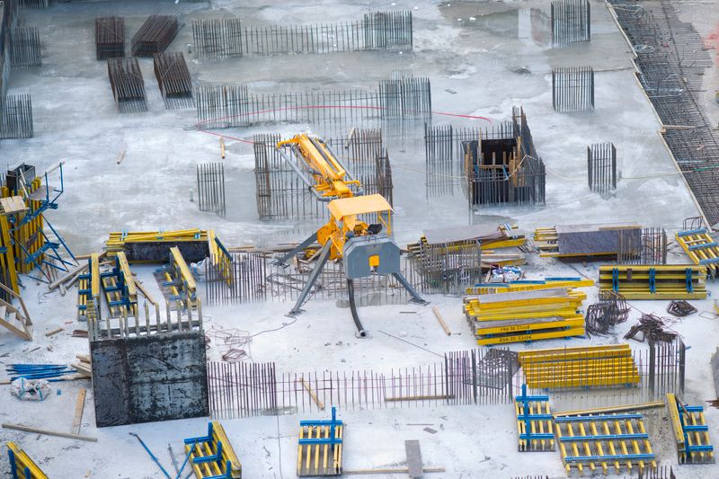
Foundation walls on church construction projects are typically 200–300 mm thick and 1200–3600 mm tall. The Advance 1 1/8″ handset forming system is an excellent choice for this work. Unlike raw plywood sheets, Advance panels are purpose-built form units — the 1 1/8″ HDO plywood face comes with steel bars and lever hardware pre-attached, ready to accept snap ties. The panels are rated for 200+ pours when maintained properly, and the system’s modular sizing means you can lay out any wall dimension without ripping plywood.
The Advance Panel System
Advance panels are not 4×8 sheets of plywood. They’re a complete forming system with steel bars, levers, and connection hardware built into each panel. Here’s what you’re working with:
| Component | Specification | Notes |
|---|---|---|
| Panel face | 1 1/8″ HDO composite (two layers HDO + one layer MDO) | APA PS-1 rated; mill-oiled faces; 200+ pour life with proper care |
| Panel widths | 4″ to 24″ in 1-inch increments | Narrow fillers (4″, 6″, 8″) eliminate field-ripping; lay out any wall length exactly |
| Panel heights | 2′ to 10′ (varies by bar system) | 8′ 4-bar and 8′ 6-bar are most common for foundation walls |
| Steel bars | Horizontal backing bars with levers | Each bar takes one snap tie; bars are pre-attached to the panel |
| Snap tie capacity | 3,000 lbs (13.3 kN) working load | 4,500 lbs max with 1.5× safety factor |
| Panel weight | 4.5–5.1 lbs/ft² | Handset by two workers; no crane required |
Bar Systems
Advance panels come in two main bar configurations, which determine the panel heights available and the tie spacing:
- 8′ 4-Bar system: Bars spaced at 20″–24″–24″–20″. Compatible panel heights: 4′ (2-bar), 6′ (3-bar), 8′ (4-bar), 9′ (5-bar), 10′ (6-bar). The lightest panels in the lineup — good for residential and light commercial foundations.
- 8′ 6-Bar system: Bars at 16″ on centre. Compatible heights: 2′8″ (2-bar), 4′ (3-bar), 5′4″ (4-bar), 6′8″ (5-bar), 8′ (6-bar), 9′4″ (7-bar). Tighter bar spacing handles higher lateral pressure — the standard choice for commercial foundation walls.
Panels can be stagger-stacked to reach wall heights up to approximately 16′. Stack a 4′ panel on top of an 8′ panel with the bar joints offset, and you’ve got a 12′ form without any site-built framing.
Connection Hardware
- Outside corners: 1″×1″ standard steel corners; bolt to the end bars of each panel.
- Inside corners: 4″×4″ steel corners for interior wall intersections.
- Offset corners: 2″ offset for stepped foundations.
- Top walers: A-style and D-style steel walers that clamp across the top of panels to align and stiffen the form line.
- Clips: Quick-connect clips that lock adjacent panels together along the bars.
- Turnbuckle form aligners: Adjustable braces for plumbing the wall. Bolt to the bar hardware and stake to the ground.
- 2′ stackers: Extension hardware for stacking panels vertically.
Pro Tip: The 1-inch-increment panel widths are one of the biggest advantages of the Advance system. Instead of ripping plywood to fill an odd gap at the end of a wall, you grab a 7″ filler panel and clip it in. Clean, fast, reusable. Keep a full set of filler widths on every job and you’ll never rip a piece of forming ply again.
Getting More Pours from Your Panels
Advance panels are rated for 200+ pours, but only if you take care of them. Follow these rules to maximize panel life:
- Oil before every pour: Apply a light, even coat of commercial form release oil to the HDO face. Don’t use diesel or motor oil — they stain the concrete and aren’t effective. Spray-on release agents give the most even coat.
- Strip carefully: Don’t pry with a flat bar against the ply face — it digs in and damages the HDO overlay. Use the lever hardware to break the form away, or tap with a rubber mallet. The form should “pop” away cleanly if it was oiled properly.
- Clean immediately: Scrape any concrete drips off the face and bar hardware while they’re still green. Hardened concrete on the bars makes it impossible to seat the snap ties properly next time.
- Stack flat: Lean panels against a wall and they warp. Stack them flat on stickers (spacer strips) to keep them true.
- Inspect hardware: Check bar levers, clips, and corner hardware for damage after every use. A bent lever or cracked clip is a blowout waiting to happen. Replace damaged hardware before the next pour.
Form Ties, Walers & Strongbacks
Form ties hold the two sides together and resist the lateral pressure of wet concrete. The pressure depends on wall height, pour rate, and concrete temperature — calculate it or use the tables in CSA A23.1. For a typical 2400 mm foundation wall poured at 1 m/hr in 15°C weather, you’re looking at roughly 35–45 kPa of lateral pressure at the base.
- Snap ties (standard): 22 kN capacity; space at 400–600 mm vertically, 600 mm horizontally for walls up to 2400 mm.
- She-bolts / taper ties: For large-format systems; reusable; 50–120 kN rated depending on diameter.
- Coil ties + coil bolts: For architectural exposed concrete (rare on foundations but common on feature walls in sanctuaries).
Think of the form as a sandwich: Advance ply face → studs → walers → strongbacks → ties holding it all together. The plywood resists the concrete surface, the studs transfer load to the walers, the walers transfer to the strongbacks, and the snap ties hold both faces together against the lateral pressure.
Assembly Sequence
- Snap chalk lines on the footing for both faces of the wall. Verify width with a tape.
- Set the first (inside) plywood form panel. If using pre-built panels, stand them on the chalk line and tack-nail the bottom plate to the footing. Plumb and brace temporarily with pipe braces or 2×4 kickers.
- Install rebar, embeds, sleeves, waterstop (see Sections 5–9 below).
- Set snap ties through the first face at the specified grid (typically 600 mm horizontal × 400–600 mm vertical).
- Set the second (outside) plywood form panel onto the tie ends. Slip the ties through pre-drilled holes in the studs and walers, then wedge.
- Install walers and strongbacks on both faces. Tighten all tie hardware — the wedge at each tie must be snug so there’s no play.
- Plumb and align using turnbuckle braces. Check plumb at each end and at mid-span with a 1200 mm level or a plumb bob.
- Final check: wall thickness (tape through tie holes), plumb (level), alignment (string line along top), and elevation of form top (laser).
I’ve seen guys spend all day setting up forms perfectly and then blow it in the last 10 minutes by not bracing properly. Concrete is patient. It waits until you’re all standing around watching the pour, and then it pushes your wall over. In front of everyone. Including the inspector.
Stripping Schedules (CSA A23.1, Table 21)
Don’t strip forms until the concrete has reached sufficient strength. The minimum times below assume normal Portland cement at ≥ 10°C:
| Member | Min. Time Before Stripping | Min. Strength |
|---|---|---|
| Foundation walls (vertical faces) | 12–24 hours | Not specified if protected |
| Columns (vertical faces) | 12–24 hours | Not specified if protected |
| Beam / slab soffits | See shoring section — P.Eng. design | 75% of f’c (typ.) |
| Cantilever slab soffits | See shoring section — P.Eng. design | 100% of f’c |
Safety: Never strip vertical forms in less than 12 hours unless cylinder breaks confirm adequate strength. In cold weather (< 10°C), extend times significantly — concrete gains strength much slower when it’s cold. CSA A23.1 Clause 21 governs. When in doubt, leave it up another day. Forms are cheaper than a wall that slumps.
3. Column Formwork (Skill 2.03)
Church buildings love columns — open sanctuaries, fellowship halls, covered entries — and columns love to go out of plumb if you let them. Two main types: round (Sonotubes or fibreglass) and rectangular (plywood or steel panel).
Sonotubes (Round Columns)
- Sizes: 200 mm (8″) to 1500 mm (60″) diameter. Most common for church projects: 300–450 mm.
- Bracing: Minimum 2 pipe braces at 90° to each other, secured to dead men (concrete blocks or staked timbers) on the ground. For columns > 3 m, add a third brace at mid-height.
- Plumb check: Use a 1200 mm level on two perpendicular faces (tape the level to the tube). Adjust turnbuckle braces until plumb reads true on both axes.
- Cutting: Score with a utility knife and snap, or use a reciprocating saw. For a clean top edge, use a string line wrapped around the tube at the cut elevation, mark with a Sharpie, and cut to the line.
Rectangular Column Forms
For rectangular columns (common in parking garages and basement structures), build with Advance 1 1/8″ forming ply (or 19 mm HDO for exposed work) on 2×4 studs at 200 mm o.c., banded with adjustable steel column clamps at 300–400 mm spacing. Clamp spacing decreases toward the bottom where pressure is highest.
Pro Tip: When placing concrete in columns taller than 3 m, use a “window” — a removable panel at mid-height or a tremie tube — to prevent segregation. Dropping concrete more than 1500 mm in free-fall causes the aggregate to separate from the paste. The result looks like a concrete Rice Krispie square, and it’s about as structural.
4. Elevated Slab Formwork & Shoring (Skill 2.04)
This is where concrete forming gets serious — and where people occasionally get killed. Elevated slab formwork means you’re holding thousands of kilograms of wet concrete above your head on temporary supports. If the shoring fails, the slab comes down. CSA S269.1 (Falsework and Formwork) and the OBC are very clear: this requires engineering.
Regulatory — Ontario Reg. 213/91, s. 85: Formwork and falsework for elevated concrete must be designed by a professional engineer (P.Eng.) licensed in Ontario. The shoring layout drawings must be stamped, signed, and available on site at all times. There are no exceptions. None. The forming foreman does not get to “figure it out” based on experience. The engineer designs it; you build it to the design.
Reshoring vs. Backshoring
After stripping an elevated slab, you often need to keep supporting it while the concrete gains full strength:
- Reshoring: Completely remove all shores and forms from under the slab, then reinstall shores (reshores) snug to the slab. The slab temporarily carries its own weight during the gap — the P.Eng. must confirm the concrete has enough strength for this.
- Backshoring: Leave the shores in place and simply loosen/reset them to transfer load to the slab below while maintaining contact. The slab never fully carries its own weight alone.
Backshoring is generally safer but more material-intensive. The P.Eng. specifies which method to use and how many levels of shores/reshores are required (typically 2–3 levels for multi-storey).
Shoring Load Calculation (Simplified Example)
For a 200 mm slab at 2400 kg/m³ density:
- Dead load of slab: 0.200 m × 23.5 kN/m³ = 4.7 kN/m²
- Construction live load (workers, equipment): 2.4 kN/m² min per CSA S269.1
- Formwork self-weight: ~0.5 kN/m²
- Total design load: ~7.6 kN/m²
- Shore capacity (typical steel frame shore): 25–40 kN per leg depending on height
- Shore spacing = capacity ÷ load per m² — the engineer works this out; you build it to the drawing
Best Practice: Shoring for elevated slabs must be inspected by the P.Eng. or their designated inspector before any concrete is placed. The inspection confirmation must be documented in writing and filed in the project QA records. No verbal approvals.
5. Rebar Tying — Footings & Foundations (Skill 2.05)
Steel reinforcement is what turns concrete from a brittle material into a structural one. Concrete handles compression beautifully; tension, not so much. Rebar handles the tension. Without it, your footing is basically a very heavy sidewalk.
Bar Sizes You’ll Encounter
| CSA Designation | Diameter | Area | Common Use |
|---|---|---|---|
| 10M | 11.3 mm | 100 mm² | Ties, stirrups, temperature steel |
| 15M | 16.0 mm | 200 mm² | Footing bottoms, slab reinforcing, wall steel |
| 20M | 19.5 mm | 300 mm² | Heavier footings, foundation walls, columns |
| 25M | 25.2 mm | 500 mm² | Grade beams, large columns, transfer beams |
| 30M | 29.9 mm | 700 mm² | Heavy structural — less common in church work |
Concrete Cover Requirements (CSA A23.1, Table 17)
Cover is the distance from the nearest concrete surface to the outside of the rebar. It protects the steel from corrosion and fire. Get this wrong and the rebar rusts, expands, and cracks the concrete from the inside — usually about 15 years after you’ve forgotten all about this pour.
| Exposure Condition | Min. Cover |
|---|---|
| Concrete cast against soil (no blinding) | 75 mm |
| Concrete cast on blinding layer / poly | 50 mm |
| Foundation walls (exterior, below grade) | 50–75 mm |
| Interior walls & columns | 30–40 mm |
| Slabs on grade (interior) | 40 mm |
| Elevated slabs (interior) | 20–30 mm |
Chairs & Spacers
Rebar doesn’t float. You need chairs to hold it at the correct elevation. Types you’ll use:
- Wire bar chairs (SB / SBU): Individual supports, set at 1200 mm max spacing. Use SBU (upper) for top mats.
- Plastic bar chairs (PBC): For slabs on grade and where wire marks on the soffit are unacceptable.
- Continuous high chairs (CHC): Long wire runners that support top bars in slabs.
- Concrete brick / dobies: For footings cast against earth. Wire chairs sink into soft subgrade — precast concrete blocks (70–75 mm) are the only reliable option on dirt.
- Side-mount spacers (wheels): Clip onto vertical bars to maintain cover from form faces in walls and columns.
Lap Splice Lengths
When bars need to be extended, you overlap them. The overlap length (lap splice) depends on bar size and concrete strength. For 25 MPa concrete (our most common footing mix):
| Bar Size | Class A Splice (tension) | Class B Splice (tension, >50% spliced) |
|---|---|---|
| 10M | 300 mm | 390 mm |
| 15M | 450 mm | 585 mm |
| 20M | 600 mm | 780 mm |
| 25M | 750 mm | 975 mm |
Stagger splices so they don’t all land in the same spot — the structural drawings will show required stagger distances. A splice is only as good as the tie wire holding it together during the pour, so tie every splice at three points: both ends and the middle.
Tie wire is cheap. Concrete repairs are expensive. If you’re wondering whether to add another tie, the answer is always yes.
6. Rebar Tying — Slabs, Walls & Columns (Skill 2.06)
Starter Bars & Dowels
Starter bars (dowels) connect footings to walls and walls to columns. They’re set into the footing pour and project vertically, ready for the next lift. Getting them in the right place is critical — they establish the wall or column location, and you can’t move them once the footing hardens.
- Spacing: Per structural drawings, typically 300–400 mm o.c. for walls, or matched to column cage verticals.
- Embedment into footing: Full development length, typically 300–600 mm depending on bar size.
- Projection above footing: Enough for a full lap splice to the wall/column steel — typically 600–1000 mm.
- Template: Build a plywood template drilled at the dowel spacing. Wire it to the footing rebar to hold dowels plumb and in position during the pour. Check with the total station before concrete placement.
Mechanical Splices
For bars 25M and larger, or where space prevents a full lap splice, mechanical couplers are specified. The two main systems:
| System | Type | How It Works | Typical Use |
|---|---|---|---|
| Lenton | Taper-threaded | Bar end is taper-threaded with a hand-held threading machine; coupler is torqued on | Wall-to-footing, column-to-footing connections |
| BarSplice | Grout-filled sleeve | Bar slides into a steel sleeve; non-shrink grout fills the annular space and bonds | Precast connections, tight spaces, large bars |
Lenton installation procedure:
- Cut the bar end square using a chop saw (not a torch — heat affects the steel).
- Thread the bar end using the Lenton portable threading tool. Verify thread engagement with the go/no-go gauge.
- Apply manufacturer’s thread lubricant.
- Thread the coupler on by hand, then torque to the specified value with a pipe wrench (typical: 135–200 N·m depending on bar size).
- Mark the coupler with paint to indicate it’s been inspected and torqued.
Best Practice: All mechanical splices must be installed by trained personnel and inspected by the superintendent. A log of coupler locations, torque values, and inspection dates must be maintained. This log is a permanent QA record — the structural engineer may request it at any time.
Wall Rebar: Putting It All Together
A typical foundation wall has two curtains (layers) of steel — near-face and far-face. Horizontal bars run the length; vertical bars run the height. They’re tied together where they cross. Here’s the sequence:
- Set the first (inside) form face.
- Install horizontal bars, starting from the bottom, wired to the starter bars.
- Install vertical bars at specified spacing, wired to horizontals at every other intersection (minimum).
- Install plastic wheel spacers on the outside vertical bars to maintain cover from the outside form face.
- Set the second (outside) form face. Verify cover by measuring through tie holes.
Pro Tip: Tie every intersection on the bottom row and the top row. For the middle rows, you can tie every other intersection — but never skip two in a row. The rebar has to stay put when 6 cubic metres of concrete hits it from a pump hose at 100 kPa. Loose bars migrate, and “migration” in rebar terms means your cover just went from 50 mm to zero.
7. Welded Wire Mesh Placement (Skill 2.07)
Welded wire mesh (WWM) is the reinforcement workhorse for slabs on grade — think fellowship halls, classrooms, hallways. It’s faster to install than individual rebar and provides uniform reinforcement. That said, it only works if it’s in the concrete, not sitting on the ground under it.
Common Mesh Sizes
| Designation | Wire Size | Spacing | Typical Slab |
|---|---|---|---|
| 152 × 152 MW18.7 × MW18.7 | 4.88 mm dia. | 152 mm × 152 mm | 100 mm residential/light commercial |
| 152 × 152 MW25.8 × MW25.8 | 5.72 mm dia. | 152 mm × 152 mm | 125–150 mm commercial slabs |
| 102 × 102 MW25.8 × MW25.8 | 5.72 mm dia. | 102 mm × 102 mm | 150 mm heavy-use slabs |
Overlap & Support
- Overlap: Minimum one full square plus 50 mm. For 152 mm mesh, that’s 200 mm. Tie overlaps at 400 mm o.c. with tie wire.
- Support chairs: Plastic slab bolsters or wire high chairs at 600–900 mm o.c. Mesh must sit at mid-depth of the slab or as specified (usually 50 mm from top for a 125 mm slab).
- The cardinal sin: Laying mesh flat on the poly, pouring concrete, and “hooking it up” with a rake during the pour. This does not work. It has never worked. It will never work. The mesh ends up on the bottom where it does approximately nothing. Place it on chairs before the pour.
I don’t care what your uncle told you — you cannot hook mesh up during a pour. That mesh goes where gravity wants it, not where you want it. And gravity wants it on the bottom. Every. Single. Time.
Best Practice: Mesh must be installed on chairs at the specified height before concrete placement. “Pull-up” or “hook-up” methods are not acceptable on church construction projects. Period. If the inspector pulls a core and finds the mesh on the bottom, the slab may need to be removed and replaced — at someone’s expense.
8. Embedded Items (Skill 2.20)
Embedded items are everything that gets cast into the concrete: anchor bolts, embed plates, pipe sleeves, electrical conduit stubs, and hold-down anchors. They’re the connection between the concrete world and everything that sits on top of it — steel, mechanical, electrical, architectural. Miss one, and someone is core-drilling your fresh concrete tomorrow. Miss several, and someone is updating their resume.
Anchor Bolt Setting with Levelling Plates
Anchor bolts for structural steel columns are the most critical embeds. A steel column base plate has bolt holes at specific locations, and those bolts need to be within ± 3 mm of design position. Rather than building plywood templates on site, the steel fabricator provides levelling plates (also called “setting plates”) — steel plates with pre-drilled holes matching the exact bolt pattern for each column. These are far more accurate than site-built templates and eliminate the risk of drilling errors. Here’s the procedure:
- Receive levelling plates from the fabricator: Each plate is labelled with the column mark (e.g., “COL-A3”) and has bolt holes matching the steel shop drawings. Verify the bolt pattern on each plate against the shop drawings before use — mistakes at the fabrication shop are rare but expensive.
- Layout: Using tape measures from the established grid lines, lay out the centre point of each column on the footing. Pull tapes from two perpendicular grid lines to triangulate each point, verify square with a 3-4-5 check, and snap chalk lines to confirm alignment. Mark the centre with a concrete nail and paint cross.
- Set the levelling plate: Centre it over the layout point. Level with a torpedo level. Wire-tie or bolt through the plate into the footing rebar cage to prevent movement during the pour.
- Set bolts: Drop anchor bolts (typically F1554 Grade 55 or 105) through the levelling plate. Set projection height with a nut and washer below the plate. Verify bolt projection matches the steel erection drawing (usually 75–150 mm above top of concrete).
- Verify bolt positions: After bolts are set and before pouring, check every bolt location by pulling tape measurements from the grid lines and cross-checking the bolt pattern dimensions with a steel tape. Compare to design — if any bolt is > 3 mm off, adjust now. After the pour, it’s $500+ per bolt to fix.
- Post-pour as-built: After concrete has cured and forms are stripped, measure and record every bolt position relative to the grid lines. This data goes to the steel fabricator for base plate verification.
Pro Tip: Double-nut your anchor bolts through the levelling plate — one nut below and one above. This locks the bolt at the correct projection and prevents it from sinking during vibration. Tape the threads above the concrete surface with duct tape to protect them from concrete splatter. Cleaning hardened concrete out of bolt threads with a die is nobody’s idea of a good time.
Embed Plates, Sleeves & Conduit
- Embed plates: Welded-on Nelson studs face into the concrete. Plates are held in place by wiring to rebar. Verify the centre of each plate by measuring from the grid lines before pour. Tolerance: ± 6 mm.
- Pipe sleeves: Typically Schedule 40 steel pipe, 2 sizes larger than the service pipe. Pack with foam plugs to keep concrete out. Wire to rebar at top and bottom. Mark the sleeve with the service type (plumbing, fire, electrical) so nobody fills it with the wrong thing later.
- Electrical conduit stubs: Set to the exact location per the electrical drawings. Bend radius per code. Cap open ends. Coordinate with the electrician — moving a conduit stub after the pour involves a hammer drill, profanity, and at least one change order.
Best Practice: An embed coordination drawing must be prepared by the superintendent before any footing or foundation pour that includes embeds. This drawing shows every bolt, plate, sleeve, and stub with survey coordinates. All trades sign off on the coordination drawing at the pre-pour meeting. No signature from a trade = their embeds don’t go in = they drill their own holes later, on their own dime.
9. Waterstop Installation (Skill 2.23)
Water has a PhD in finding ways through concrete. Construction joints — the cold joints where one pour meets the next — are its favourite path. Waterstop is the seal that blocks that path. Two main types:
PVC Waterstop
A flexible PVC strip (typically 150–230 mm wide, 5–10 mm thick) with a centre bulb and ribbed wings. The wings embed in the concrete on both sides of the joint; the centre bulb allows for joint movement.
- Placement: Centre the waterstop on the construction joint. Half embeds in the first pour, half projects into the second pour.
- Support: Wire-tie to a horizontal rebar or use a split-form detail to hold it centred in the wall thickness. It must be centred — if it drifts to one side, there’s not enough embedment on that side and it won’t seal.
- Splicing: Heat-weld PVC waterstop with a thermostat-controlled iron at 200–230°C. Butt-fuse, not overlap. Overlap joints leak — always. Factory-made crosses, tees, and corners are available and recommended for complex intersections.
- Corners & intersections: Use factory-fabricated fittings. Field-welding corners is possible but error-prone. A bad corner splice is worse than no waterstop at all because it gives everyone false confidence.
Hydrophilic Waterstop
A swelling rubber strip (e.g., Adeka P-201 or Sika SikaWaterbar) that expands 200–300% when exposed to moisture. Simpler to install than PVC but single-use — once it swells, it can’t be re-used.
- Application: Nail or adhesive-bond to the surface of the first pour before placing the second pour. No embedment needed — it sits on the joint surface.
- Spacing: Centre on the wall thickness. Must be continuous — gaps defeat the purpose.
- Protection: Keep it dry before the second pour. Rain or standing water will cause it to swell prematurely. Cover with poly if rain is expected.
- When to use: Horizontal construction joints in foundation walls, where PVC waterstop installation would be impractical. Also used at pipe penetrations as a secondary seal.
Regulatory: OBC Section 9.13 (and Part 5 for larger buildings) requires below-grade structures to be protected against water infiltration. Waterstop at all construction joints in below-grade walls is standard practice. The engineer of record specifies the type and locations — don’t omit it, even if “it’s just a footing joint.” Water doesn’t care what you think is “just” anything.
10. Vapour Barrier (Skill 2.24)
The vapour barrier under a slab on grade prevents moisture from wicking up through the concrete and ruining flooring, causing mould, or turning the fellowship hall into a swamp. It sounds simple — lay plastic on the ground — but the details matter enormously.
Material Selection
| Type | Thickness | Permeance | When to Use |
|---|---|---|---|
| Standard polyethylene | 6 mil (0.15 mm) | ~0.06 perms | Minimum code requirement; Not recommended for church projects |
| Heavy polyethylene | 10 mil (0.25 mm) | ~0.03 perms | Recommended for interior slabs with hard flooring |
| Premium vapour barrier | 15 mil (0.38 mm) | < 0.01 perms | Recommended for slabs receiving moisture-sensitive finishes (hardwood, VCT, carpet) |
Best Practice: Minimum 10 mil poly on all slabs on grade. Upgrade to 15 mil under any slab receiving moisture-sensitive flooring (hardwood, VCT, LVP, carpet). No exceptions. The cost difference between 10 mil and 15 mil is about $0.15/ft². The cost of replacing buckled hardwood in a 5,000 ft² sanctuary is about $75,000. Do the math.
Installation Procedure
- Granular blinding layer: Before laying poly, ensure the granular base (typically 19 mm clear crush or pea gravel) is graded smooth with no sharp stones protruding. Sharp aggregate punctures poly. A 50 mm blinding layer of sand or fine crush on top of the structural granular is ideal.
- Roll out the poly: Start at one wall and unroll across the slab area. Cut with a utility knife. Handle gently — don’t drag it across rough stone.
- Lapping: Overlap all joints by minimum 150 mm (recommended: 300 mm). Tape all laps with poly-compatible tape (e.g., Tuck Tape or manufacturer-specified). Butyl tape for premium barriers.
- Turn up at edges: Run the poly up the inside face of the foundation wall or edge form by at least 100 mm. This prevents moisture from entering at the slab-to-wall joint.
- Penetrations: Cut the poly tight to any pipes, columns, or sleeves penetrating the slab. Seal around penetrations with compatible tape. Every hole is a moisture path — treat each one like a potential leak.
- Protect during rebar/mesh installation: Walk on the poly with care. Place plywood walkways if heavy rebar or chairs are being installed. Patch any tears immediately with tape and a poly patch piece (min 300 mm overlap on all sides of the tear).
The Great Debate: Poly Directly Under Slab or Under Granular?
Some old-school specs call for a sand layer on top of the poly (between the poly and the concrete) to “reduce curling.” This is outdated advice. Current best practice (per CSA A23.1): place the vapour barrier in direct contact with the concrete. A sand layer on top of the poly creates a reservoir that traps bleed water and actually makes moisture problems worse. Best practice is poly directly under concrete — no sand cushion on top.
I once had a flooring installer tell me the slab was “sweating.” Slabs don’t sweat. Slabs don’t have pores. What they have is a vapour barrier with a 6-inch gap in the lap that nobody taped. Twenty minutes with a roll of Tuck Tape could have saved $40,000 in flooring replacement.
Pro Tip: Before the concrete pour, do a “vapour barrier walk” with the foreman. Walk every square metre. Look for tears, untaped laps, and poly that’s been pulled away from edges or penetrations during rebar installation. This 15-minute walk can save months of flooring warranty headaches. Bring a roll of tape and fix problems on the spot.
Quick-Reference: Pre-Pour Checklist
Before every concrete pour, the forming foreman and superintendent walk through this list. No shortcuts, no “we already checked that yesterday.” Yesterday was yesterday. Things move overnight — especially when there’s a backhoe parked next to your forms.
- Forms: Plumb? Level? Correct dimensions? Braced? Oiled/released? Tight joints?
- Rebar: Correct size, spacing, and cover? Tied securely? Chairs/spacers in place? Splices correct length?
- Embeds: All anchor bolts, plates, sleeves, and conduit in place? Surveyed? Coordinates verified?
- Waterstop: Continuous? Properly centred? Splices heat-welded (PVC) or continuous (hydrophilic)?
- Vapour barrier (SOG): Intact? Laps taped? Turned up at edges? Penetrations sealed?
- Access: Truck access clear? Pump location confirmed? Chute reach verified?
- Inspection: Municipal inspector called? Structural engineer notified (if required)?
- Weather: Forecast checked? Cold weather protection ready (blankets, ground heaters) if < 5°C?
- Documentation: Pre-pour checklist signed by foreman and superintendent. Pour slip ready.
Safety: Concrete burns are real and serious. Fresh concrete is highly alkaline (pH 12–13) and will cause chemical burns on prolonged skin contact. Wear rubber boots (not leather — it soaks through), long sleeves, gloves, and safety glasses. If concrete gets inside your boots, wash immediately. A concrete burn can progress to a third-degree injury without you feeling it until hours later. This isn’t dramatic — it happens every season on construction sites across Ontario.
Trade Certification & Continuing Education
In Ontario, concrete formwork and reinforcement falls under the Cement (Concrete) Finisher (310C) and Reinforcing Rodworker trades. While not all positions require Red Seal certification, it is strongly encouraged. The knowledge you gain in the apprenticeship program directly applies to every section of this training guide.
- 310C — Cement (Concrete) Finisher: 3-year apprenticeship, 3 in-school sessions (8 weeks each). Covers placing, finishing, forming, and curing.
- 420A — Ironworker (Reinforcing): 3-year apprenticeship. Covers rebar fabrication, placement, tying, and post-tensioning.
- Forming Carpenter: Falls under 403A — General Carpenter in Ontario. Formwork is a significant module in the carpentry apprenticeship.
You can learn formwork in a week. You can get decent at it in a year. It takes about ten years before you can look at a set of forms and just know they’re right. The good news is, you’re building churches — and churches are patient. They’ll wait for you to learn. The concrete, on the other hand, will not.
Best Practice: All forming crew leads must have a minimum of 5 years’ experience in commercial concrete formwork or hold a valid 403A certificate with formwork endorsement. Rebar tying crews must include at least one 420A-certified ironworker or equivalent. These requirements are documented in the project quality plan and are strongly recommended for church construction projects.
Recommended Videos
-
Concrete Formwork Fundamentals
YouTubeAn overview of concrete formwork systems including wall forms, column forms, and slab forming techniques used in commercial construction.
-
Rebar Placement & Formwork Assembly
YouTubeDemonstrates proper rebar tying, placement tolerances, and formwork assembly procedures for foundation walls and footings.
-
Stripping Forms & Quality Checks
YouTubeCovers form removal timing, surface inspection after stripping, and common defects to watch for in finished concrete surfaces.